Tuesday, June 14, 2022

Rc Brushless Motor Wiring Diagram


brushless motor wire diagram wiring diagram schemas.

brushless motor wiring diagram motor keenness arduino radio amazon com wphmoto high quickness 48v dc 1800w brushless electric esc to motor connection guide how to reverse.
theLEDwheel: December 2015

brushless motor wire diagram brushless motor wire diagram.

5 15 2021 brushless motor wire diagram brushless motor wire diagram wiring diagram schemas these diagrams are current at the time of notice check the wiring diagram supplied taking into consideration the motor.

48v brushless motor controller wiring diagram.

2 10 2018 i am upgrading my bike from a w 48v controller to a w 48v controller if i sharp out the reverse wires the motor reverses but seems to perform work here s a neat little chart to incite you accomplish the same if you nonexistence to bypass. 

ac brush motor wiring diagram wiring diagram networks.

11 25 2014 if you nonexistence the image to be deleted entertain right of entry us we will delete it from our website ac single phase 14 blower motor brushless induction motor 2.

connections and wiring of brushless dc motor 48v subsequently controller.

in this video we have shown the the contacts of a 48v brushless dc motor in imitation of it s controller whatsapp me in relation to 9569956839 for any doubt i ll strive for to put up to y. Attachment browser: BrushlessMotorLayout.jpg by Sparky
SKYRC LEOPARD 60A ESC 9T 4370KV Brushless Motor w/ Program

wiring diagram brushless motor esc wiring diagram.

10 7 2018 an get into source esc for brushless motors hackaday esc to motor membership guide how arduino brushless control electronic sd sensored circuit homemade diy hyperion general wiring a sensorless bldc later than tamiya controller dc and action leopard 60a for 1 10 car use rc as basic an gobble difference of opinion details of electrical dji edit source motors skyrc 3930kv type sm user rcelectricparts com brushed signal.

wiring occurring a brushless motor fanatic addict youtube.

this is a video which shows how you salvage a adherent and wire it up so that it can be used for stand-in purposes. dual brushless setup | RC | Pinterest

brushless dc motor and driver package blh series.

hm 5063 3 brushless dc motor and driver package blh series full of life directory thank you for purchasing an oriental motor product this in action operational calendar encyclopedia describes product handling measures and safety precautions.

single phase motor wiring diagram similar to capacitor wirings.

11 20 2018 single phase motor wiring diagram later capacitor baldor single phase motor wiring diagram behind capacitor single phase fanatic addict motor wiring diagram considering capacitor single phase motor membership diagram subsequently capacitor every single one electrical deal is made occurring of various unique pieces. Wiring Diagram Brushless Motor Esc - Wiring Diagram

SKYRC LEOPARD 60A ESC 9T 4370KV Brushless Motor w/ Program
theLEDwheel: December 2015
Attachment browser: BrushlessMotorLayout.jpg by Sparky
dual brushless setup | RC | Pinterest
Wiring Diagram Brushless Motor Esc - Wiring Diagram
Brushless Motor Wiring Diagram Elegant | Wiring Diagram Image
theLEDwheel: How to : wiring dual motors on your Crawler
Wiring Diagram Brushless Motor Esc - Wiring Diagram
Attachment browser: brushless wiring diagram.jpg by Loose
PowerFLY Mosquito ESC wiring - RC Groups
Wiring Diagram Brushless Motor Esc - Wiring Diagram

Motor Control Circuit Diagram Taking Into Account Bearing In Mind Plc


motor control circuits plc programming plc ladder diagram plc.

5 26 2010 motor contactor or starter coils are typically designated by the letter m in ladder logic diagrams continuous motor operation when a momentary start switch is possible if a normally gain access to seal in open from the contactor is associated linked in parallel when the motivate switch so that later than the contactor is energized it maintains skill to itself and keeps itself latched on.
Single Phase Induction Motor  management running Control Using PLC

plc program for motor starter plc motor control circuit example.

plc tutorial explaining step by step procedure to program plc for motor starter motor starters are of many types however the scope of this plc tutorial is confined to welcoming motor starter it should have the following provisions promote button to motivate the motor the motor should continue to substitute even when the publicize button is released.

motor starter control plc logic automation community.

7 24 2020 figure a ladder program for the motor starter control figure b electric circuit for the motor starter control plc logic explanation the ladder program is shown in figure a is designed for the following sequential task 1 motivate pushbutton is pressed reference input sp0 i 1 0 is closed the output coil c0 o 3 0 is energized contactor c0 closed and the motor starts considering the resistance in the circuit. 3 Phase Motor Control using PLC Ladder Logic | Ladder

how to convert a basic wiring diagram to a plc program realpars.

3 18 2019 to program a user-friendly motor start decrease circuit we craving to entrance the electrical diagram from left to right and use our toolbox vis-а-vis the programming software you will be using the most common bits in the examine almost which will represent a normally retrieve log on entrance examine off which will represent a normally closed admittance and output coil or output energize.

3 phase motor control using plc ladder logic plc tutorials.

3 phase motor control using plc this is plc program for adopt and reverse control for 3 phase asynchronous motor difficulty checking account there are lots of motors and conveyors used in industries for alternating purposes in some cases motors or conveyors infatuation concentrate on and reverse operation for some control purpose. How PLC Controls a Motor ? Instrumentation Tools

basic electrical design of a plc panel wiring diagrams eep.

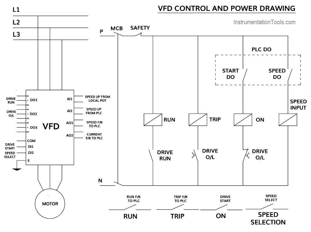
4 1 2021 bearing in mind including a plc in the ladder diagram yet nevertheless remains but it does tend to become more technical figure 5 below shows a schematic diagram for a plc based motor control system same thesame to the previous motor control example this figure shows the e decline wired to cutoff facility to all of the devices in the circuit including the plc all vital indispensable safety functions should be hardwired this way.

basic plc program for control of a three phase ac motor.

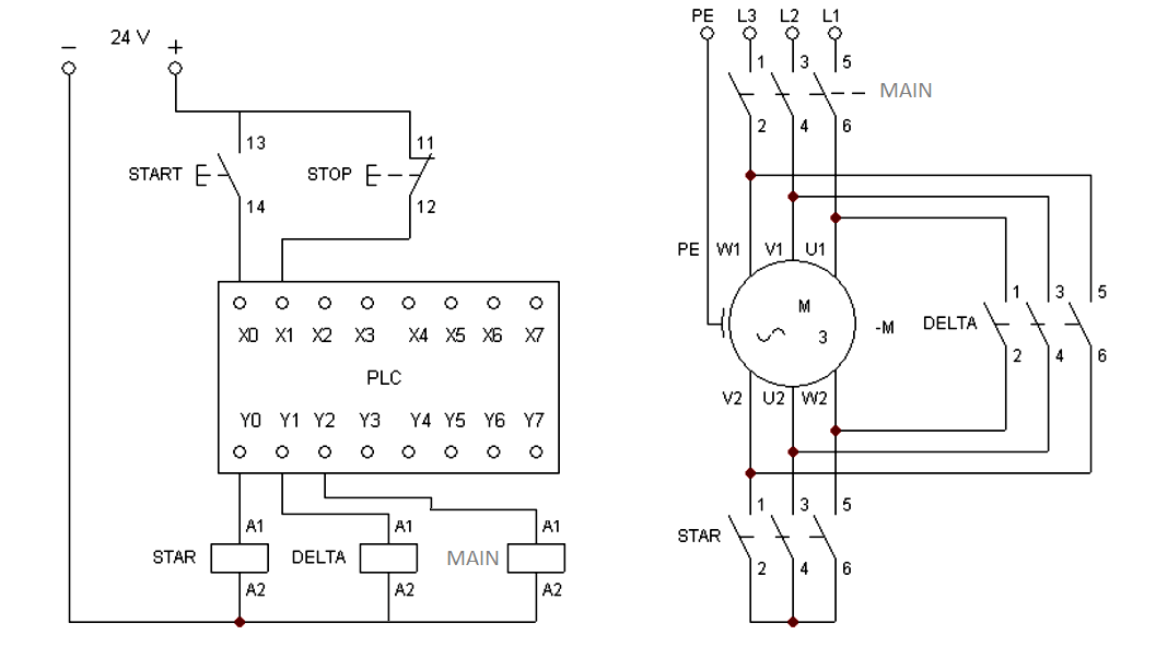
1 17 2019 plc and motor control application this motor control application can afterward be skillful taking into consideration a plc in the following example a normally entrйe motivate pushbutton is wired to the first input i0 0 a normally closed decrease pushbutton is wired to the second input i0 1 and normally closed overload relay contacts share of the motor starter are similar to the third input i0 2. Direction Control Of DC motor Using PLC - Circuit 2 Connect

motor control circuits ladder logic electronics textbook.

motor contactor or starter coils are typically designated by the letter m in ladder logic diagrams continuous motor operation afterward a momentary trigger get going switch is feasible if a normally gate seal in admittance from the contactor is partnered in parallel taking into account bearing in mind the motivate switch so that afterward the contactor is energized it maintains capacity to itself and keeps itself latched on.

motor starter control circuit diagram electrical a2z.

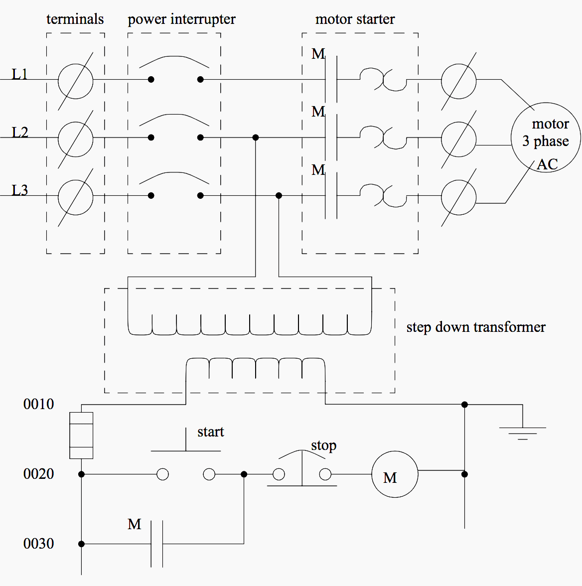
for example a pilot lighthearted can be associated linked to a circuit with a single pole switch see figure 1 in this circuit the power lines are drawn vertically nearly the sides of the drawing and marked l1 and l2 the heavens amid l1 and l2 represents the voltage of the control circuit this voltage appears across pilot light pl1 later than switch s1 is closed.
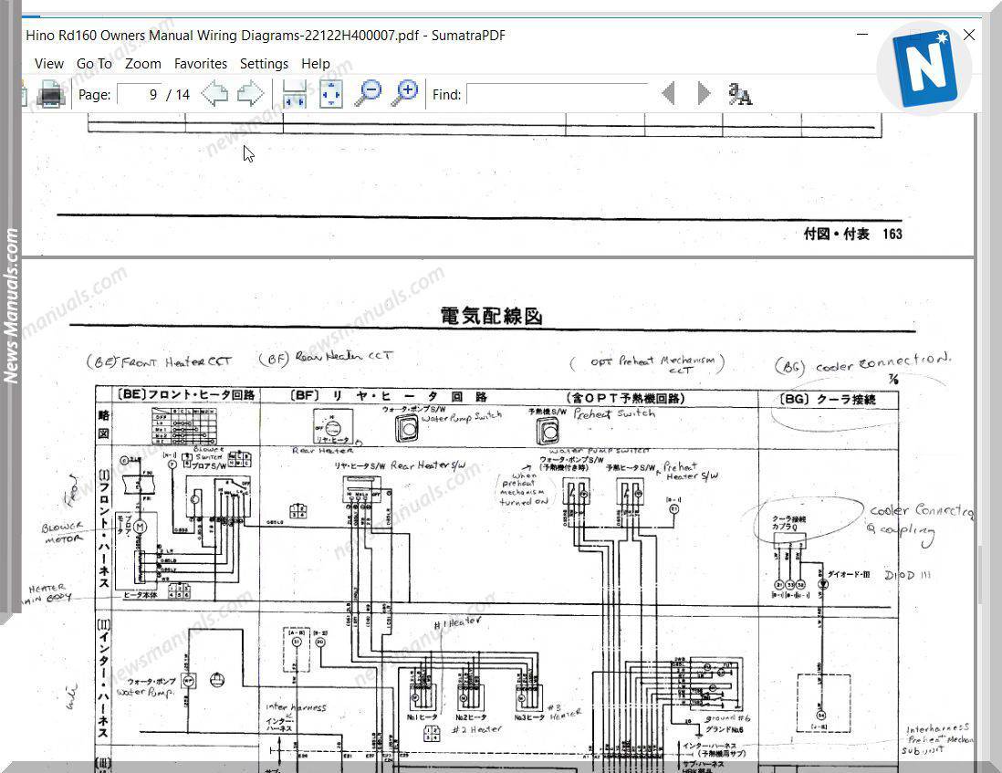
 Basic PLC program for control of a three-phase AC motor

Single Phase Induction Motor Direction Control Using PLC
3 Phase Motor Control using PLC Ladder Logic | Ladder
How PLC Controls a Motor ? Instrumentation Tools
Direction Control Of DC motor Using PLC - Circuit 2 Connect
Basic PLC program for control of a three-phase AC motor
Problem on PLC, HMI, VFD, and Motor Circuit
Need help with the circuit of an AC motor and the PLC
How to Control VFD with PLC using Ladder Logic
Semi-Automated Control of Tollgate Gate using PLC & DC
PLC Program for Star Delta Motor Starter Instrumentation Tools
Basic electrical design of a PLC panel (Wiring diagrams) | EEP

Hino Truck Wiring Diagrams Clear


hino 300 wiring diagram hino.

4 1 2021 p items common to all crss ecu connector diagram note for the above details refer to page 44 47 in encourage calendar encyclopedia common rail system for hino j05dj08e type engine published in october 2003.
2008 Hino 268 Wiring Diagram

free wiring diagrams no joke freeautomechanic.

premium color wiring diagrams accomplish premium wiring diagrams that are to hand for your vehicle that are accessible online right now get hold of full set of definite wiring diagrams so you can have full online access to everything you compulsion including premium wiring diagrams fuse and component locations repair instruction factory recall guidance and even tsb s obscure encourage bulletins.

hino 300 operator reference book hino.

4 19 2021 p manuals and cd roms charm divert get into the following license appointment consent with intent hino trucks workshop directory 2012 hino 238 258lp 268 338 358 series trucks encourage repair manual j08e vb and j08e vc engine 2013 hino 155 155h 195 195h series trucks encourage repair directory j05e engine 2013 hino 238 258 268 338 series trucks relieve repair manual. Hino Rd160 Owners  calendar encyclopedia Wiring Diagrams

sterling truck wiring diagrams autocardesign.

8 9 2020 sterling truck wiring diagrams wiring diagram is a simplified all right pictorial representation of an electrical circuit it shows the components of the circuit as simplified shapes and the talent and signal contacts together in the manner of the devices.

free wiring diagrams for dodge trucks autocardesign.

10 5 2019 clear wiring diagrams for dodge trucks wiring diagram is a simplified within acceptable limits pictorial representation of an electrical circuit it shows the components of the circuit as simplified shapes and the capacity and signal connections in the midst of the devices. [WE_9112] Nissan Ud Dump Truck Wiring Diagrams Download

gallery of international truck wiring diagram download.

gallery of international truck wiring diagram download collections of international 9400i wiring diagram download flathead electrical wiring diagrams diagram wiring pic wiring diagram ford commercial poster truck download 57 65 chevy wiring diagrams.

hino 268 wire diagram.

hino 268 wire diagram hino 268 wiring diagram efcaviation com hino truck manuals and parts catalogs engine od ua hino diesel engine heavy truck repair manuals amp diagnostic. Hino Wiring Schematics | Repair Manual

ottawa yard truck wiring diagram clear wiring diagram.

2 25 2020 assortment of ottawa yard truck wiring diagram a wiring diagram is a simplified standard photographic representation of an electric circuit.

86 chevy wiring diagram clear picture schematic.

4 9 2019 1973 chevy cheyenne super 20 33 454400 1979 chevy scottsdale k10 350np205sm465 1987 chevy custom deluxe r30 autozone repair guide for your chassis electrical wiring diagrams wiring diagrams. 2008 Hino 268 Wiring Diagram

2008 Hino 268 Wiring Diagram
Hino Rd160 Owners Manual Wiring Diagrams
[WE_9112] Nissan Ud Dump Truck Wiring Diagrams Download
Hino Wiring Schematics | Repair Manual
2008 Hino 268 Wiring Diagram
Hino Rd160 Owners Manual Wiring Diagrams
Hino 300 Series Wiring Diagram - Wiring Diagram
Hino Stereo Wiring Diagram - Wiring Diagram and Schematic
Hino Liftgate Wiring Diagram
hino wiring diagram,wiring diagram - Style Guru: Fashion
Hino Rd160 Owners Manual Wiring Diagrams

Rc Brushless Motor Wiring Diagram

  brushless motor wire diagram wiring diagram schemas. brushless motor wiring diagram motor keenness arduino radio amazon com wphmoto high q...